- Join Newsletter & Get 10% Off Your First Order

Join / Login
Rigging tips for building a model ship.
- Updated on: 25th January 2021
- Written by Gary Renshaw
Introduction
Rigging is a significant part of the process of building a model ship. It can be tedious and time-consuming however putting the effort in adds to the beauty of your finished model.
In general, the instructions on rigging provided by the manufacturers of model ship kits are fairly sparse. Whilst there are several specialised and very detailed books on masting and rigging, they are more concerned with matters of historical and technical accuracy than with the sort of advice that might help the beginner to understand the best way of going about what might appear to be quite a daunting task.
Highly recommended is a 3 DVD set available from Modellers Shipyard on Masting and Rigging . This is a comprehensive set which shows all aspects of preparing the masts, spars and yards and the rigging for a period model. For further information call our office or visit our website.
We do strongly recommend “Ship Modelling Simplified” by Mastini – it contains excellent advice on ship modelling in general and has a good section on rigging. Modeller’s Shipyard has produced the following information as an introduction to the Rigging of a model ship. The following points should be noted:
- This is a general guide only and is to be used in conjunction with any instructions and plans provided by the kit manufacturer. In particular, it must be emphasised that any illustrations used in this leaflet are purely for the purpose of example and may not relate to your specific model.
- The approaches described are not the only way of doing things and the order in which the various processes are carried out may be varied, within reason, to suit the individual modeller.
Building a model ship is as much an exercise in using the mind as it is in using your fingers and hands. In this small leaflet, we can’t hope to cover all the problems and queries that may be encountered in the construction of your model. It is necessary to spend as much time thinking about the task at hand as actually doing it. If having thought about it, you still have a problem then contact us. We’ll either be able to advise you ourselves or refer you another modeller in your area who’ll be happy to help you with “hands-on” assistance.
TYPES OF RIGGING
The rigging of a ship can be divided into two main parts:
- “Standing” or “Fixed” rigging, which is used to support the Masts and Bowsprit.
- “Running” rigging, which is used to manipulate spars and sails.
On an “actual” ship any Rigging which didn’t pass through a pulley block was coated with tar to help prevent it rotting. For this reason, standing rigging is often, although not always, black on ship models.
If you do want your standing rigging black, and black cord is not supplied in the kit then you can consider these options:
- You can purchase Black cord.
- The use of black rigging “wax” gives a very authentic tarred look but it is difficult to do well.
- The cord supplied with the kit can be coloured using black dye or “Raven Oil” as used by leatherworkers/saddlers.
- Black felt-tipped “Texta” is an easy way to colour the cord.
- Black “Padawax” shoe colour is also very satisfactory.
When any liquid dye has been used it will be necessary to stretch the cord by hanging it on a clothesline, with weights, to prevent it going slack after installation on the model. It will also probably be necessary to use clear wax to eliminate any furry look in the cord.
STANDING RIGGING
This includes the rigging of the Stays, Backstay, Bowsprit and Gammoning. This is fairly straightforward and should present few difficulties. Work from the centre of the ship out and try to avoid difficult and confined spaces. A Rigging Tool presented in the Tools section of our Catalogue will be helpful when rigging. The various names for the standing rigging are presented below.
- Fore topmast stay
- Fore topgallant stay
- Flying-jib stay
- Fore royal stay
- Fore skysail stay
- Main topmast stay
- Main topgallant stay
- Main royal stay
- Main skysail stay
- Mizzen stay
- Mizzen topmast stay
- Mizzen topgallant stay
- Mizzen royal stay
- Mizzen skysail stay
- Mizzen topmast backstay
- Mizzen royal backstay
- Mizzen skysail backstay
- Main topmast backstay
- Main topgallant backstay
- Main royal backstay
- Main skysail backstay
- Fore topmast backstay
- Fore topgallant backstay
- Fore royal backstay
- Fore skysail backstay
- Bowsprit shrouds (bobstays)

Source: “Ship Modeling Simplified” by Mastini Pages 143 –144
FITTING OF BLOCKS, EYE PINS & CLEATS
Before proceeding further fit all the eye pins and rigging blocks to the bowsprit, masts, yards, and deck – also to the insides of the bulwarks if required. Cleats may be required on the lower masts, deck or bulwarks. Pay particular attention to any area which will be relatively inaccessible once the shrouds and other standing rigging ropes are in place.
It is as well to drill out the holes in the blocks and deadeyes to facilitate the threading of the rigging cord when the time comes.
For the most inaccessible blocks, insert a short piece of thin rigging cord through the hole and glue it to itself forming a loop. Later, when you wish to insert the permanent running rigging you cut the loop, glue the new cord to one end and pull it through the hole using the other end of the pilot cord. No awkward threading
DEADEYES (LOWER) AND CHAIN STRAPS/ DEADEYE STRAPS
In most models, the lower deadeyes are fitted into “deadeye loops” which are inserted into gaps in the outer edge of the “Channel”. Once the complete row of deadeyes are installed a capping strip is fixed along the front.
From the bottom of the deadeye loop either a straight ”Deadeye Strap” or a “Chain Strap” goes to the side of the hull at a lower level. The style of this fitting will depend on the period to which the particular ship belongs and also the price/ quality of the ship being built.

There are several points to keep in mind when setting up these “deadeye assemblies”
The deadeye strap (or chain strap) is rarely, if ever, perpendicular. Rather, it should be at an angle which is an extension of the angle of the shroud which will eventually be attached to the deadeye above it. The diagram on the left of this page should make that mouthful clearer!!
The lower deadeyes, the ones being attached at present, should be placed so that the three holes are positioned with the lowest one being the centre of the three. When at a later stage the upper deadeye is fitted, it is equally important that the centre hole is the highest of the three. Refer to the diagram on the right-hand side of this page.

These together with the “forestays” and “backstays” are the ropes that support the masts. Shrouds, which are the group of ropes to which the ratlines are attached, are made up in pairs with a deadeye at each end of a single rope.
First cut a piece of cord to an appropriate length and with the help of an alligator clip or a small clamp glue one end around a deadeye. This deadeye should then be temporarily connected to the front portside (left hand) lower deadeye using a wire jig. This jig will provide the correct spacing between the upper and the lower deadeye.

The loose end of the rope then goes up, around the mast and down to the position of the lower deadeye immediately behind the first. Using glue, alligator clip and another wire spacer, the upper deadeye is attached to the shroud. At a latter stage, the double thickness of cord immediately above the upper deadeye will be bound with fine thread as shown as shown in some of our diagrams. The “Lanyards”, made of the thinnest rigging cord, are then installed as shown in the adjoining drawing. Because on the “real thing” the lanyards were constantly used to take up tension on the shrouds they were never tarred and should not be black.
Once the first pair of shrouds has been completed, the exercise is repeated on the other (starboard) side, then, back to the port side and so on.
If, when the others have been done there remains a single lower deadeye on each side then the final pair of shrouds goes from one side of the ship to the other with a large seized eye around the masthead. In all of this, it is important to ensure that the deadeyes are in straight rows parallel with the channels and with each other.

SEQUENCE OF SHROUDS

The forestays should now be fitted paying attention to the particular fittings used. Quite commonly “heart deadeyes” and lanyards will be used for tensioning purposes.

These are always rigged with a large seized eye around the masthead as with the “odd” shrouds (if any). As with the shrouds they are rigged with deadeyes and lanyards but the upper deadeye will normally be at a higher level than that of the shroud deadeyes.
The colour of the ratline cord is grey or fawn. The tying of ratlines can be fairly tedious but it is worth going to some trouble to ensure that it is done well. Among the points to keep in mind are:
- They should not be too tight otherwise they will pull the shrouds together.
- They should be parallel to the waterline.
- On the “real thing” the spacing between each row was about 400mm so, on a model at a scale of say 1:50, the gap would be approximately 10mm.
- Avoid tying knots tightly until all the ratlines are in place. This will allow some “fine tuning” before placing a tiny dab of glue on each knot. Placing a sheet of white plain paper behind the shrouds will assist with gaining contrast to make the tying of the ratlines a tad easier on the eyes.

ATTACHING RIGGING LINE TO BELAYING PINS
The adjacent diagram demonstrates clearly the method best used to attach the cord to the belaying pins.
If you have any difficulties determining which belaying pin a rope is intended to go to, a good rule of thumb is that the higher up the mast it starts then the further back it finishes.

ROPE COILS
Plenty of rope coils draped over the belaying pins provide a finishing touch. These can be made from odd lengths of offcuts. If placed into the shapes you require they can be (fixed) permanently by using hair lacquer or nail polish.
WHAT SIZE ROPE TO USE
In the plans or in the instructions there should be a key or description of the size of cord to be used for various purposes. In the unlikely event that no indication is given, then the following can serve as a guide:
Forestays & Anchor ropes – Heavy cord
Shrouds & Backstays – Medium cord
Ratlines & Running Rigging – Lightest cord
RUNNING RIGGING
Once the standing rigging has been completed you can now start the Running Rigging. You will have enlarged the holes in the blocks which are already in place. Do the same with all other blocks as you come to use them.
When threading cord through blocks, you will find that a needle threader (available from sewing shops) will be very handy. Also, a smear of super glue on the end of the cord can stiffen it and make it easier to thread. Work from the centre of the ship out and try to avoid locking yourself into difficult positions. A Rigging Tool presented in the Tools section of our Catalogue will be helpful when rigging.
The various names for the Running Rigging are presented below.
- Fore brace
- Fore lower topsail brace
- Fore upper topsail brace
- Fore lower topgallant brace
- Fore upper topgallant brace
- Fore royal brace
- Fore skysail brace
- Fore yard lift
- Fore topsail yard lift
- Fore topgallant yard lift
- Fore royal yard lift
- Fore skysail yard lift
- Main lower topsail brace
- Main upper topsail brace
- Main lower topgallant brace
- Main upper topgallant brace
- Main royal brace
- Main skysail brace
- Main yard lift
- Main topmast yard lift
- Main topgallant yard lift
- Main royal yard lift
- Main skysail yard lift
- Mizzen yard brace
- Mizzen lower topsail brace
- Mizzen upper topsail brace
- Mizzen lower topgallant brace
- Mizzen upper topgallant brace
- Mizzen royal yard brace
- Mizzen skysail yard brace
- Mizzen topmast yard brace
- Mizzen topgallant yard lift
- Mizzen royal yard lift
- Mizzen skysail yard lift

Source: “Ship Modeling Simplified” by Mastini Pages 145 –146
TYPICAL RUNNING RIGGING APPLICATIONS

NAMES OF MASTS & SPARS
- Fore lower mast
- Fore topmast
- Fore topgallant mast
- Fore royal and fore skysail mast
- Main lower mast
- Main topmast
- Main topgallant mast
- Main royal & main topgallant mast
- Mizzen lower mast
- Mizzen topmast
- Mizzen topgallant mast
- Mizzen royal & mizzen skysail mast
- Fore topsail yard
- Fore upper topsail yard
- Fore lower topgallant yard
- Fore upper topgallant yard
- Fore royal yard
- Fore skysail yard
- Main lower topsail yard
- Main upper topsail yard
- Main lower topgallant yard
- Main topgallant yard
- Main royal yard
- Main skysail yard
- Crossjack yard
- Mizzen lower topsail yard
- Mizzen upper topsail yard
- Mizzen lower topgallant yard
- Mizzen upper topgallant yard
- Mizzen royal yard
- Mizzen skysail yard
- Gaffsail boom
- Flying-jibboom
- Martingale boom, dolphin striker

Source: “Ship Modeling Simplified” by Mastini Pages 142 –143
Key Takeaways
- The article provides practical rigging tips for model ship builders, focusing on both standing and running rigging techniques.
- Emphasizes the importance of understanding different types of rigging and their applications in model ship construction.
- Offers advice on materials and tools needed for effective rigging, including how to choose the right cord size for various rigging parts.
- Highlights techniques for making rigging tasks simpler and more efficient, such as coloring cords and preparing blocks.
- Advises on the order of operations for rigging, suggesting starting with standing rigging before moving to running rigging.
Learn The Art Of Building A Model Ship
Get started in wooden model ship building today
Join 18,543 other modelers to hear about specials, new products and modeling tips
- Become a Member
- Modeling Hub
- Model Ship Building
- Maritime History
- Affiliate Program
Information
- Terms & Conditions
- Privacy Policy
Copyright © 2023 Modelers Central. ABN: 31 114 830 732
- Claim 10% Off First Order
- Get 5% off ALL orders with a Membership
- Gift Vouchers
- Help & Advice
Modelers Central. 2023, All rights reserved.
- Claim 10% Off Your First Order
- Get 5% Off All Orders With A Membership
Get 10% off
Your first order.
10% off applies only to full-price items. By providing your email address, you agree to our Terms & Privacy Policy
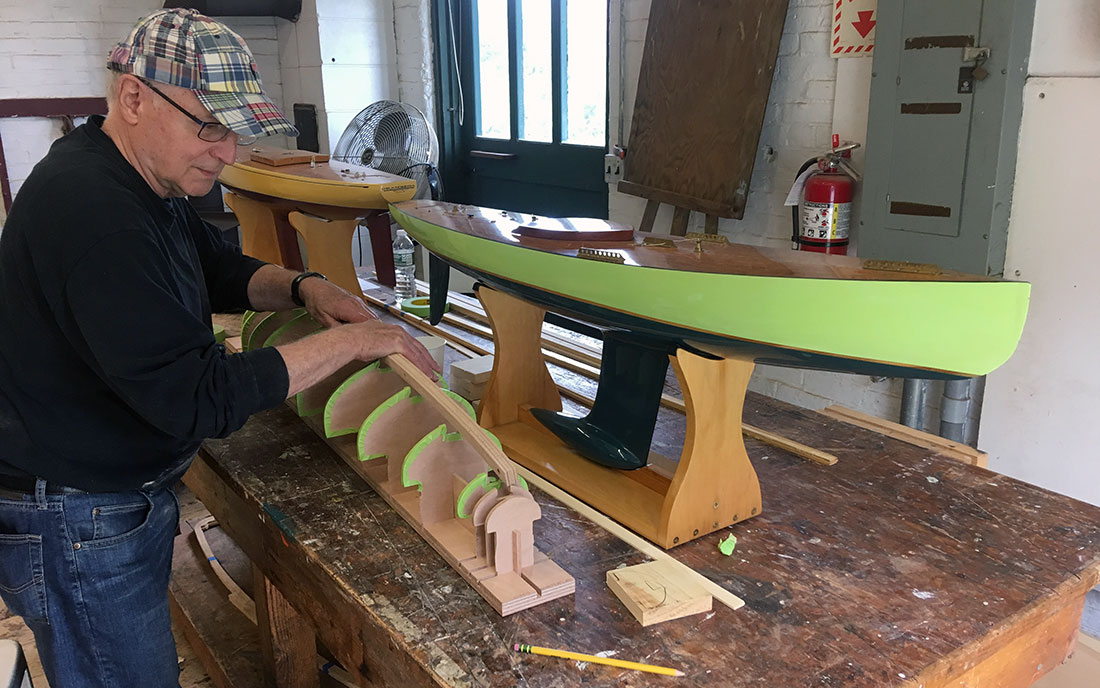
A Pond Yacht Restoration
I am restoring a pond yacht, built by my grandfather , James Melville and a Mr. Ingram in Tayport, Scotland, in the early 1930s. The hull is 55 inches long x 13 inches at it's widest point ( beam ). The mast is 62 inches tall and the boom is 33 inches long. She weighs 26lb. The measurements and weight and classic lines are consistent with a classic 6 Metre yacht design, popular with model yacht builders in the 1930s.
Monday 30 March 2015

No comments:
Post a Comment
- Fair American
- Tools and Techniques
- Kit Database
- Bluenose Canadian Schooner
Bowsprit Rigging
May 9, 2017
With the bowsprit built , it is time to add all the rigging. This will be the first bit of rigging I’ll be doing on the Bluenose, by design. I intentionally did the bowsprit before any of the masts so I could get my feet wet with the rigging before I start on more critical rigging that actually holds stuff in place.
On my Model Shipways Phantom build , I took a lot of shortcuts on the rigging. In most cases, I simply tied the lines off. On the Bluenose, I’m going to try to do things more correctly (although my limited skills will cause me to do things that might make an experienced modeler cringe).
I’m going to set up the rigging before mounting the bowsprit. Doing the rigging off-the-ship seems to be the recommended method. This makes it easier to do all the little work each line requires without having to work around other lines, masts, booms, etc.
The first step is to fully understand what I’m doing. Even the simple rigging for the bowsprit has a lot of parts. For someone like me, who isn’t familiar with all the terminology and standard parts, knowing exactly what each line requires is difficult. Personally, I find the rigging plans hard to read.
So, I spent some time mapping out each line, and created my own rigging plans. I made two sheets – one for most of the rigging, and one specifically for the foot ropes.

The rigging plan I created for the bowsprit.
The basic rigging for the bowsprit involves a few different lines:
- The backropes are found on both the port and starboard side. These connect to the small ring at the very end of the bowsprit and run back to the rail on the bow.
- The guys are also found on both port and starboard, and connect to the larger ring on the bowsprit, and run to the hull.
- The upper bobstay and lower bobstay run from the bottom of the bowsprit to the front of the bow.
Using the plans, I also mapped out all the hardware involved. This required flipping between several different drawings of the bowsprit and its rigging. I identified a few different pieces of hardware that I’ll need.
- Staples are ‘U’ shaped pieces of metal that go into the ship, allowing things to be attached to them.
- Links are like links in a chain – an oval loop of metal – and used to connect things to staples.
- Plates are strips of metal that are bolted to the hull, similar to the chain plates.
- Shackles are generally ‘U’ shaped, but have holes at the tips to allow a pin to be passed through, securing them to something.
- Turnbuckles are more complex assemblies that have rings on either end, attached to screws, allowing a line to be tightened.
I also worked up a plan for the foot ropes…

The rigging plan for the foot ropes.
The foot ropes are just two ropes that run from the ring on the end of the bowsprit back to the hull. However, these lines have some slack in them so they hang down a little. Sailors would use these to walk on when they needed to get out to the bowsprit. To keep them stable, some stirrups run from guy-to-guy, tied off on the foot ropes.
So, with my plans prepared, I set out to make all the hardware.

Staples are easily made by bending wire.
The staples were easy to make from 22 gauge brass wire. Short pieces of wire were simply bent around a pair round-nose pliers. These will be trimmed to their appropriate lengths when they get installed.

Links are made from wire.
Links were also easy to make. Some wire is just wrapped around and cut.

Shackles were a little more tricky. A common way to make shackles is to bend some wire around. My first attempt at this turned out pretty good, but I realized they were WAY too big. To get them smaller, I had to use thinner wire. However, even with my thinnest wire, they looked pretty bad.

Early attempt at shackles using wire. Tough to get to scale, and they look pretty bad.
So, I decided to try a different approach. I decided to try making the shackles from brass strip, bent into a ‘U’, with holes drilled in either end. To make them a little fancier, I’ll try using my milling machine to shape them.
I took some 1/16″, 1/64″ thick brass strip and glued it down to a piece of scrap wood. I determined that my pieces needed to be about 8mm long before being bent, so I marked that on the wood. I drilled a hole in each end of each piece, making several at once.

Making shackles from brass strip – starting with drilling the holes.
Once the holes were drilled, I moved the assembly over to the milling machine. With the brass still glued down, I used my mill to carve away a little bit of the brass strip on either side, between the holes. This wasn’t a precision job – I just eyeballed it.
The brass was then removed from the wood, and the pieces were cut apart.

Brass strips for shackles after drilling, milling, and cutting to length.
They don’t look great when they first come off, but they look a lot better once they’re bent into shape.
Each one was bent using round nose pliers.

Shackle being bent to shape.
I made some temporary pins from brass wire. Here you can see the whole shackle assembly.

Completed shackle made from brass strip.
The last big piece of hardware is the turnbuckle. Turnbuckles are basically impossible to make accurately at this scale, and many different ways to ‘fake it’ are out there. I decided to try making my own, using a process I detailed here .

Turnbuckles made from brass rod and tube.
The other parts, like the plates, will be made when I need them.
Now I just need to install everything. As mentioned before, I’m going to do as much as I can with the bowsprit off the ship, sitting on a little stand I made.
I started with the upper and lower bobstays, then did the guy lines. The basic process is to cut some rigging line (with a good amount extra) and attach it to the bowsprit using whatever hardware is called for by the plans. The other loose end is coiled up and taped to keep things tidy.
On the bowsprit, all the lines are secured using an eye splice. This is basically a loop in the end of the rope, made by weaving the rope back into itself. I got some great tips from others on the Model Ship World forum for making these, and I detailed my method here .
Below you can see the guy lines attached to the ring band using shackles and turnbuckles. The bobstays are secured to the bottom of the bowsprit.

The guy lines and bobstays attached to the bowsprit.
All the lines are run back to the stand, coiled up, and taped off.

Lines are coiled up and secured to keep them organized.
The backropes are installed next. These run from the front ring and are attached using shackles. You’ll notice that I started using large pieces of wire bent into an ‘L’ shape as the pins for shackles. I did this so that I can easily remove the pin and take the rope lines off. This will be helpful once I start attaching the rigging to the hull.

Backropes are added.
The photo above shows all the rigging ready to go. The loose ropes at the front are the foot ropes. I tried to make those off the ship (shown here), but later ended up taking them off and remaking them. It was nearly impossible to get the length right (and get the right amount of slack) while the bowsprit is off the ship.
With the lines ready, it is time to actually install the bowsprit. This just requires sliding it through the hole in bow. I applied a little bit of CA glue on the white end of the bowsprit to secure it in place.

The bowsprit is installed.
With the bowsprit installed, I can now finish up a couple non-rigging things. There are two details that couldn’t be completed when the bowsprit was initially built because they can’t go on until the bowsprit is installed.
The first detail is the jumbo jib traveller block . This is a little piece that sits on top of the bowsprit and holds one end of the jumbo jib boom. The piece was carved from a strip of basswood according to the plans and painted white.

The jumbo jib traveller block is made from strip wood. The wire is NOT glued in yet.
Two notes on the jumbo jib traveller block. First – the bottom must be shaped so it sits nicely on the bowsprit. Since the bowsprit is round, the bottom of the block needs to be curved to match it. Second – the block has a wire on top where the jumbo jib boom hooks on. This wire should not be glued in now . I’ll need to be able to slide the ring of the jumbo jib boom on here, and that won’t be possible if the wire is glued in.

The jumbo jib traveller block installed on the bowsprit.
The next piece is the gammon iron . This is a metal piece that wraps around the bowsprit right at the bow and secures it to the hull. This can be made from a single strip of brass, but I decided to make it more realistic.
To make it, I took a pice of brass 1/16″ x 1/64″ brass strip and folded it in half. I drilled a hole in the top and glued in some brass rod. This ‘bolt’ will secure the two halves of the gammon iron together.
I trimmed off the excess rod and also cut off the fold in the top. Next I bent the pieces around the bowsprit to get the right shape, then drilled some holes through the lower areas where bolts will secure it to the hull.

The completed piece was then filed a bit to clean it up.

The completed gammon iron made from brass strip.
The gammon iron was placed over the bowsprit right at the bow and secured with a little bit of CA glue on the lower parts. Then some more brass rod was glued into those holes to simulate bolts. As done with the chain plates and rudder pintles+gudgeons , these were trimmed off once the glue dried.

The gammon iron being installed, with brass rod to simulate bolts.
With those two items complete, the ‘construction’ of the bowsprit is done and I can get back to rigging.
The backropes were attached first. These are attached to staples that go into the rail, just forward of the catheads. The lines use an eye splice to attach to turnbuckles, and the turnbuckles attach to the staples.

Backropes are attached to staples in the rail.
This is where being able to unhook the shackles on the bowsprit comes in handy. Once the turnbuckle is attached to the staple, the line is pulled through it and tightened. Then I mark the exact spot in the line where the eye splice needs to happen, and remove the line from the ship. Now I can do that eye splice (including wrapping it) off the boat, then install it back on.
Next up were the guy lines. These attach to plates that are mounted to the hull. The plates have a bolt on one end and a staple on the other. I used more of my favorite 1/16″ x 1/64″ brass strip here. The three holes were drilled and the strip was painted black, then it was glued in place. The fake bolt and the staple were then installed.
The guy lines were then attached to these plates using an eye splice and a shackle.

Plates are installed on the sides of the hull for the guy lines.
The bobstays attach to plates that seem to wrap around the keel at the bow. At first glance it looks like these might be done similar to the gammon iron, but they are actually separate pieces on either side of the hull, with a pin running between them.
I make these plates according to the plans. The plates for the upper bobstay are shorter than the ones for the lower bobstay.

The plates for attaching the bobstays to the bow.
These were glued on either side of the hull at the right locations, then fake bolts were added as I’ve done elsewhere. A piece of brass rod was used to make the pins that run through the single holes at the end. An eye splice and a link secure the bobstays to the pins.
All that’s left at this point are the foot ropes and jib stops. As mentioned earlier, the foot ropes I made off the ship were the wrong length. I pulled those off and started over (again, good thing my shackles are removable.
The foot ropes attach to staples below the rail on each side up by the bow. I installed these, then made new foot ropes that were extra-long and only had an eye splice on one side. Those were secured back on the bowsprit, then run through the staples. I adjusted the length until I was happy with them, then added the eye splices on those ends and attached them to the staples with shackles.
To keep the foot ropes from swaying too much, stirrups connect them to the guy lines. I found these tough to do correctly, so I faked it. I think the right way to do this is to tie a line to the guy line on one side, then run it to the nearby foot rope, tie it, run it to the other foot rope, tie it, then run it to the other guy line and tie it off. When I tried that, I had a really hard time keeping everything hanging right. Tying four knots in one line made it difficult to keep the right amount of slack in the line.
So, I did it this way:
- Tie the stirrup to one guy line.
- Run it under the foot ropes and up to the guy line on the other side.
- Tie it to the other guy line, being sure to leave the right amount of slack so it has the right curve.
- Use black thread to tie the foot ropes to the stirrups.
- Secure all the knots with a little dab of CA glue.
This didn’t turn out perfect, but it is ok . I’ll see if this still looks sub-par to me over the next few weeks, and if so I’ll remove the foot ropes and guy lines and redo them.

Foot ropes and stirrups installed.
The last thing to add are the jib stops. These were short ropes used to tie down the jib sail. Unlike the rest of the bowsprit rigging, these are made from tan rope.
I cut several short pieces of rope and tied knots in the ends. These knots will keep the jib stops from falling out of their holes.

Jib stops are made by tying knots in short pieces of tan line.
Each piece was trimmed at the knot and placed through one of the holes along the top of the bowsprit. They were secured with a little dab of CA glue, then trimmed to a consistent short length.

Jib stops dropped into their holes along the top of the bowsprit.
And that’s it! The bowsprit is now done.
You’ll notice that I still have the big ugly wires in the shackles. Those are going to stay for a little longer. Leaving those in gives me the option of redoing those foot ropes if they start driving me crazy. Also, I’m waiting on an order of some small brass bolts that might make great shackle pins. So until those arrive, the ugly wire stays.

The completed bowsprit, still with ugly wire for pins.

The ship is now too long to fit on the shelf I’ve been using when I need to get it out of the way.
With the bowsprit done, I’m ready to start working the fore mast.
- Click to share on Twitter (Opens in new window)
- Click to share on Facebook (Opens in new window)
- Click to share on Reddit (Opens in new window)
- Click to share on Tumblr (Opens in new window)
- Click to share on Pinterest (Opens in new window)
- Phantom NY Pilot Boat
- Model Ship Kit Database
Copyright © 2018 SuburbanShipModeler.com The text, photos, and content are copyright of this site unless otherwise noted.
Photos were taken by the author unless otherwise noted. All brands and trademarks referenced are the property of their respective owners.
Discover more from The Suburban Ship Modeler
Subscribe now to keep reading and get access to the full archive.
Type your email…
Continue reading
Pond Sailboat Rigging
by L. Novak (Houston, TX)
| | | | |
|
| |
| I have the same problem. My schooner was built by my father and I too received only the hull. I am trying to restore it for it's original owners 82th birthday. Time is of the essence! |
Click here to add your own comments
Return to Model Boats Q&A.
| Facebook Twitter |
Would you prefer to share this page with others by linking to it?
- Click on the HTML link code below.
- Copy and paste it, adding a note of your own, into your blog, a Web page, forums, a blog comment, your Facebook account, or anywhere that someone would find this page valuable.
- Plans Store
- Model Boat Books
- Model Boats Intro
- Building Materials
- Make a Hull
- Plastic Kits
Radio Control
- US Battleships
- Torpedo Boats
- Model Boats Q&A
- Model Ship Gallery
- What's New?
- Privacy Policy

By Petter Blix
Copyright 2009-2018 Building-Model-Boats.com
Trademarks belong to their respective owners
All Rights Reserved
- Search forums
- Practical Boat Owner's Reader to Reader
Pond yacht Project
- Thread starter Quandary
- Start date 18 Feb 2010
- 18 Feb 2010
Well-known member

I don't know if your model is based on a full-sized prototype, but the GB Model Yachting Assn. administer a National 36" class. The dimensions of 36" x 9" that you quote would fit in with that rule. There is also a depth limit of ~11". AFAIK, no other dimension is controlled

http://www.modelboatmayhem.co.uk/forum/index.php
Thanks guys, I thought I knew a bit about boats but the stuff on the model yacht sites is way, way above my head. Why do they need to use different names for everything. The prices of bits they sell suddenly make yacht chandlers look cheap too. This is a home (school) built boat so I was hoping I could stay with the diy approach. I would prefer to use real yacht technology rather than try to get to grip with the model yacht jargon. Like a lot of hobbies their sites seem to be aimed at those in the know. My main questions How best to make a mast that will support a mainsail, preferably in a slot.(the present one is just tapered Douglas Fir with a taut wire up the back instead of a groove) How to put together a convincing looking jib and main ( I am temped to make the jib one piece and just draw or tape seams on it) Should I use monel wire or something else for the standing rigging. I think I can make or adapt a convincing gooseneck, spreaders, chainplates, running rigging etc. Having accepted the gift I feel obliged to persevere, but my work will be judged to quite high standards, perhaps I should just hide it in the attic.
For rigging wire use nylon covered stainless steel trace wire & crimps from fishing tackle shops. Sails are probably better of made from dacron, nylet sails used to be a good supplier. As for the mast it wont be easy to put a luff groove in but it could be done if the mast is built up from two halves with small groove cut in each side on small circ saw blade then the groove sanded out. There is a Vintage model yacht group that might be worth a try.

Twister_Ken
Wouldn't mast hoops be more in keeping?

Identity? No, the keel is different and the hull sweeps up until there is virtually no transom. By the way, it has come to me from Belfast so perhaps not Scottish.

fishermantwo
Active member.
I have just about finished the third one of these for my grandkids. Hulls are stripped plank timber, cedar and epoxy. The keels are wing keels made of stainless steel, They stand up with out stands for display purposes. Masts and booms are maple and cedar just saturated in epoxy. Rigging is 40lb braid fishing line, its spectra. Deck fittings are SS shark fishing clips. For sails I imported a few metres of 2 ounce dacron from England. The main is loose footed and for shape I cut in a bit of luff round. Thats all you need. The jib will sag off a bit so it has negative luff round. LOA is 58 cm. The only problem so far is the speed, they are a bit fast. I used to build my own model yachts as a kid. The technology available now makes it so much easier.
- 19 Feb 2010
Many if not most model yachts use an extruded section mast with luff groove already formed and use the same section for the boom and loose footed mainsails; this makes the fitting of backstay and spreaders easy ,and the kicking strap fits into the luff groove (the groove is underside of the boom). Model Yachts magazine have several suppliers for the bits and pieces,and unless you are making her a radio controlled job the expense will be minimal. I used to build 1 Metre class yachts,and they have a measurement diagram for the sail plan which might help for proportions. If she's too tall perhaps convert to a yawl or a ketch and shorten the mainmast. When you make the sail the luff edge can be folded and doublesided taped over a piece of twine, to suit the luff groove, you may not need to sew as well then. Get your wire rigging from the local fishing tackle shop and some crimps and fine swivels and clips. ianat1982
As usual the information supplied is relevant and useful, so my thanks to everyone who took the time to help me. No excuse not to make a start now, unless it warms up and I go sailing.
- 20 Feb 2010
I had an interesting learning experience with a pond yacht some years ago. As some have observed, their proportions are different to real yachts. years ago, I made a "J class-esque" flush-decked model and found that it was ridiculously over-canvassed. It dawned on me that they can't really be scale copies of anything "real". The buoyancy varies with the cube of the linear dimensions (I think) and the sail area with the square of the linear dimensions of the rig. For that reason, the rigs don't look quite right and / or the keels are massively long to provide a suitable righting moment.
Other threads that may be of interest
- 24 Jul 2024
Members online
- Openelectron
- John_Silver
- Orion_surprise
- dave_gibsea
- Corkysailor
- john_morris_uk
- CaptnPugwash
- Slipstream 34
- simonfraser
- onemanorthree
- Wandering Star
- Porthandbuoy
- Rocksteadee
Share this page
- New Sailors Guide
- SAILSetc DRAWINGS
- 3D PRINT A YACHT !
- MAST, BOOM & RIGGING PARTS
- RIGGING Wire/Spectra/Dyneema
- HULL & DECK FITTINGS
- VANGS - GOOSENECKS
- BOOM SECTIONS
- MASTS Alum & Carbon Fibre
- RIG KITS & RIG PLANS
- FINS AND BULBS
- BOATS - KITS & PLANS
- RG65 - MICRO MAGIC - Parts
- SAILS & SAILMAKING
- WINCHES & DRUMS
- RADIOS SERVOs BATTERIES etc
- POND YACHTS & PARTS
- ACCESSORIES, COVERS & MISC.
- FASTENERS Screws, Bolts, Nuts
- SPARE PARTS
- CLEARANCE ITEMS
- FREE Boat & Rigging Plan Links
- PARTS DRAWINGS
- Print your own CATALOGUE
- Shipping Info
- Privacy Policy
- Conditions of Use
- Newsletter Unsubscribe
- Create Account
- Shopping Cart
| | :: POND YACHTS & PARTS to (of products) to (of products) |
Standing Rigging (or ‘Name That Stay’)
Published by rigworks on november 19, 2019.
Question: When your riggers talk about standing rigging, they often use terms I don’t recognize. Can you break it down for me?
From the Rigger: Let’s play ‘Name that Stay’…

Forestay (1 or HS) – The forestay, or headstay, connects the mast to the front (bow) of the boat and keeps your mast from falling aft.
- Your forestay can be full length (masthead to deck) or fractional (1/8 to 1/4 from the top of the mast to the deck).
- Inner forestays, including staysail stays, solent stays and baby stays, connect to the mast below the main forestay and to the deck aft of the main forestay. Inner forestays allow you to hoist small inner headsails and/or provide additional stability to your rig.
Backstay (2 or BS) – The backstay runs from the mast to the back of the boat (transom) and is often adjustable to control forestay tension and the shape of the sails.
- A backstay can be either continuous (direct from mast to transom) or it may split in the lower section (7) with “legs” that ‘V’ out to the edges of the transom.
- Backstays often have hydraulic or manual tensioners built into them to increase forestay tension and bend the mast, which flattens your mainsail.
- Running backstays can be removable, adjustable, and provide additional support and tuning usually on fractional rigs. They run to the outer edges of the transom and are adjusted with each tack. The windward running back is in tension and the leeward is eased so as not to interfere with the boom and sails.
- Checkstays, useful on fractional rigs with bendy masts, are attached well below the backstay and provide aft tension to the mid panels of the mast to reduce mast bend and provide stabilization to reduce the mast from pumping.
Shrouds – Shrouds support the mast from side to side. Shrouds are either continuous or discontinuous .
Continuous rigging, common in production sailboats, means that each shroud (except the lowers) is a continuous piece of material that connects to the mast at some point, passes through the spreaders without terminating, and continues to the deck. There may be a number of continuous shrouds on your boat ( see Figure 1 ).
- Cap shrouds (3) , sometimes called uppers, extend from masthead to the chainplates at the deck.
- Intermediate shrouds (4) extend from mid-mast panel to deck.
- Lower shrouds extend from below the spreader-base to the chainplates. Fore- (5) and Aft-Lowers (6) connect to the deck either forward or aft of the cap shroud.
Discontinuous rigging, common on high performance sailboats, is a series of shorter lengths that terminate in tip cups at each spreader. The diameter of the wire/rod can be reduced in the upper sections where loads are lighter, reducing overall weight. These independent sections are referred to as V# and D# ( see Figure 2 ). For example, V1 is the lowest vertical shroud that extends from the deck to the outer tip of the first spreader. D1 is the lowest diagonal shroud that extends from the deck to the mast at the base of the first spreader. The highest section that extends from the upper spreader to the mast head may be labeled either V# or D#.
A sailboat’s standing rigging is generally built from wire rope, rod, or occasionally a super-strong synthetic fibered rope such as Dyneema ® , carbon fiber, kevlar or PBO.
- 1×19 316 grade stainless steel Wire Rope (1 group of 19 wires, very stiff with low stretch) is standard on most sailboats. Wire rope is sized/priced by its diameter which varies from boat to boat, 3/16” through 1/2″ being the most common range.
- 1×19 Compact Strand or Dyform wire, a more expensive alternative, is used to increase strength, reduce stretch, and minimize diameter on high performance boats such as catamarans. It is also the best alternative when replacing rod with wire.
- Rod rigging offers lower stretch, longer life expectancy, and higher breaking strength than wire. Unlike wire rope, rod is defined by its breaking strength, usually ranging from -10 to -40 (approx. 10k to 40k breaking strength), rather than diameter. So, for example, we refer to 7/16” wire (diameter) vs. -10 Rod (breaking strength).
- Composite Rigging is a popular option for racing boats. It offers comparable breaking strengths to wire and rod with a significant reduction in weight and often lower stretch.
Are your eyes crossing yet? This is probably enough for now, but stay tuned for our next ‘Ask the Rigger’. We will continue this discussion with some of the fittings/connections/hardware associated with your standing rigging.
Related Posts
Ask the Rigger
Do your masthead sheaves need replacing.
Question: My halyard is binding. What’s up? From the Rigger: Most boat owners do not climb their masts regularly, but our riggers spend a lot of time up there. And they often find badly damaged Read more…
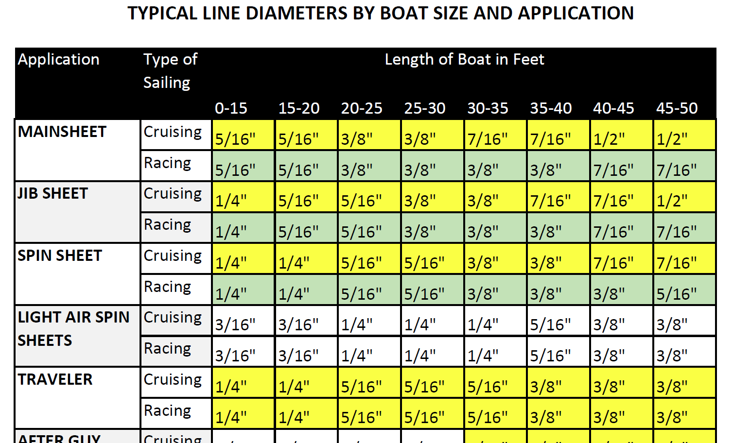
Selecting Rope – Length, Diameter, Type
Question: Do you have guidelines for selecting halyards, sheets, etc. for my sailboat? From the Rigger: First, if your old rope served its purpose but needs replacing, we recommend duplicating it as closely as possible Read more…
Spinlock Deckvest Maintenance
Question: What can I do to ensure that my Spinlock Deckvest is well-maintained and ready for the upcoming season? From the Rigger: We are so glad you asked! Deckvests need to be maintained so that Read more…
The global authority in superyachting
- NEWSLETTERS
- Yachts Home
- The Superyacht Directory
- Yacht Reports
- Brokerage News
- The largest yachts in the world
- The Register
- Yacht Advice
- Yacht Design
- 12m to 24m yachts
- Monaco Yacht Show
- Builder Directory
- Designer Directory
- Interior Design Directory
- Naval Architect Directory
- Yachts for sale home
- Motor yachts
- Sailing yachts
- Explorer yachts
- Classic yachts
- Sale Broker Directory
- Charter Home
- Yachts for Charter
- Charter Destinations
- Charter Broker Directory
- Destinations Home
- Mediterranean
- South Pacific
- Rest of the World
- Boat Life Home
- Owners' Experiences
- Conservation and Philanthropy
- Interiors Suppliers
- Owners' Club
- Captains' Club
- BOAT Showcase
- Boat Presents
- Events Home
- World Superyacht Awards
- Superyacht Design Festival
- Design and Innovation Awards
- Young Designer of the Year Award
- Artistry and Craft Awards
- Explorer Yachts Summit
- Ocean Talks
- The Ocean Awards
- BOAT Connect
- Between the bays
- Golf Invitational
- BOATPro Home
- Superyacht Insight
- Global Order Book
- Premium Content
- Product Features
- Testimonials
- Pricing Plan
- Tenders & Equipment
.jpg/r%5Bwidth%5D=320/c01b08f0-3198-11ec-b3da-5dc06521023f-Black%20Pearl%20-%20Tom%20Van%20Oossanen%20(3).webp "pond yacht rigging diagram")
The definitive guide to sailing yacht rigging
Related articles, superyacht directory.
Do you know your Bermudan rig from your DynaRig or wingsails? And which is best? BOAT explains it all...
Take a look at a modern racing yacht from above, beating to windward and heeled to the breeze, and you can see at a glance why Bermudan rigs have stood the test of time. With its fore and aft sails bladed into efficient aerodynamic shapes, a modern yacht can slice close to the wind and be driven hard. Such a sight would have been outlandish a century ago. Then, a typical trading barquentine could set 18 sails to catch light airs, but it needed a large crew to battle with canvas far out on the yards. In a modern miracle as incredible in its way as flight, today’s racing yachts can sail faster than the speed of the wind – in some cases several times faster.
A mainsail set on a single spar is an age-old concept but only in the 19th century was it adapted as the Bermudan or Marconi rig. A one-piece mainsail set on a mast without a gaff, hoisted with one halyard and controlled by one sheet, was simpler and more efficient. This revolution became the power train of pleasure yachting and racing.
But perhaps the time is coming for a re-evaluation of simpler rigs requiring fewer crew – alternatives with lower loads operated by automated systems. In an era of reduced carbon consumption, could more radical sailplans even herald a revival in sail power?
The evergreen Bermudan rig
The Bermudan rig is the all-rounder, able to perform well at all angles of sail. It is efficient upwind, while downwind the sail area can be significantly boosted with a big gennaker or spinnaker. For good reasons, it is the first choice for nearly every modern sailing yacht up to around 60 to 65 metres for cruising and regatta racing alike. At larger sizes, however, things start to become trickier, and the trade-offs get interesting.
Over the last decade, sail handling technology has steadily advanced to allow sloop rigs to grow larger and larger. “But with that comes a highly loaded rig, many tonnes of compression from tension in the rigging, and you have to build structure in the boat to accept that,” explains Paul MacDonald, founder and superyacht sales manager of Southern Spars.
“You have to have a lot of deck gear and captive winches below decks and the machinery for that. But over the years, boom furling systems and MPS [Multi Purpose Sails for downwind angles] stored on a drum, for example, have made sail handling safer.
Bill Tripp is the designer behind the 86-metre Aquijo , which broke new ground in 2015 as the world’s largest Bermudan ketch. Tripp prefers to call the rig a "sketch", a portmanteau word for a rig that is neither a sloop nor a ketch “because the main and mizzen are identical”. Even though the sailplan is divided over two masts, each spar is still a towering 90 metres above the water. Aquijo perfectly illustrates the issues involved with a Bermudan rig when scaled up.
“The sloop is great but I prefer the ‘sketch’ for sailing around the world under full control due to the desirability of a two-masted rig for reaching ability, which dominates passages, and the safety of controllable loads when sailing in all kinds of conditions miles from nowhere,” he says.
Upwind, Aquijo sets a jib, staysail, mainsail and mizzen, all in North Sails 3Di, totalling 3,821 square metres. A furling Code sail for reaching and downwind angles increases that to a vast 5,051 square metres.
While Aquijo has a crew retinue of 17, it can be controlled under sail by six or seven people. With custom winches to handle halyards and sheets, the sails can be hoisted astonishingly quickly for such a large rig. “It takes five minutes to put the main up, on average, and the main and mizzen can go up at the same time,” Tripp says. Aquijo has now sailed 100,000 nautical miles around the world and the owner is planning another circumnavigation through the Northwest Passage.
Tripp is not convinced of the wisdom of a much larger single-masted sloop rig. “If you are day sailing in the Med, a sloop would be awesome, but I am not sure if you had fewer sails you would be able to [reduce canvas] well enough. Also the mast is a windage problem when the keel is up and you are beam-to. If you are on anchor, that’s no problem but you’d have to be able to cope with being on the docks in 70 knots. The windage at 120 metres is not only more but the centre of effort is so much higher, and so the heeling loads all go up.”
However, British designer Malcolm McKeon , the name behind the high-performance, sloop-rigged carbon composite superyachts Missy and Ribelle , is pushing the sloop rig to new heights. His 85-metre design concept Apex, developed with Royal Huisman , would be the largest sloop-rigged yacht in the world. “The loads are enormous,” he admits, “but it is all scalable.”
“The big disadvantage is sail handling. The downwind sails are pretty complicated once you start hoisting and retrieving, even with drum and reel systems. It is not straightforward.” But, he adds, “I think we know the advantages of a sloop: if you want all-round performance you can’t beat it, even at the top end.”
Advantages of a clipper rig
The DynaRig has been around as a concept since the 1960s when German engineer Wilhelm Prölss devised these free-standing, rotating rigs as a fuel-saving solution for large commercial vessels. The idea was ahead of its time, so much so that its first realisation came nearly 40 years later when American owner Tom Perkins bought the residual technology and commissioned Dykstra Naval Architects to create a three-masted DynaRig for Maltese Falcon , his 88-metre Perini Navi.
The DynaRig is not as efficient upwind as the Bermudan rig, and is probably not the best solution for a yacht smaller than around 65 metres, suggests Jeroen de Vos of Dykstra. “We wouldn’t advise putting a DynaRig on a small yacht because there are other ways to manage sail handling. But on a larger yacht the DynaRig becomes an alternative because there is no rigging, no highly loaded sheets, low-tech [small] sails and no big winches.”
The beauty of the DynaRig is that its automatic systems can be handled by one or two people and, notes de Vos, “you don’t have to get out of your chair to go sailing. Maltese Falcon can sail on and off the anchor and can set 2,400 square metres of sail in six minutes. On other boats it takes six minutes to get the sail cover off.”
Damon Roberts of Magma Structures, which built the rigs for Maltese Falcon and the only other DynaRig yacht to date, the 106-metre Black Pearl , says: “You can do any manoeuvre easily; it’s like sailing a dinghy. There are no highly loaded sheets or ropes or flogging lines. You can luff up, bear away, tack and gybe at any time and really enjoy sailing the boat without any apparent fuss.”
So with all these advantages, why has the DynaRig been chosen for only two sailing superyachts? For some designers, such as Malcolm McKeon, it is partly to do with compromises imposed by the large mast tubes and bearing diameters on the internal structure and layout, “particularly in the cockpit area,” he says. He also points out that the clipper ship look is not to every owner’s taste. “Sloops are more conventional looking,” he says.
Damon Roberts says there is still development work to be done. He has teamed up with Southern Spars and, with their additional resources, expects evolution with several new projects. “These include two at the moment that are twin-masted DynaRigs,” he says. “We did quite a lot of wind tunnel work early on as we felt that was really the sweet spot for it, and people will be stunned at how efficient these are.”
The future of the wingsail
Wingsails have been around for decades too, but with their adoption by the last two America’s Cups and the confluence with foiling technology, they have undergone rapid and revolutionary development.
To date, there is no proven solution for reefing a wing that would be suitable for offshore cruising or ocean passages. As the pronounced aerodynamic “nose” at the leading edge of a wing can develop force in strong winds, they could potentially make a large yacht uncontrollable in port as well.
“How do you get rid of sail and how does [a boat] handle when caught out in heavy wind conditions – which you will be? How do you keep the angle of attack all the way up the rig and how do you handle squalls?” Roberts asks. “A mechanism to reduce sail might be easy to sketch out but it is difficult to engineer.”
Jeroen de Vos says: “The wingsails are more developed towards performance and I wouldn’t say that they are as practical as soft sails or would ever make handling easier. But if somebody wants that, why not? Reefable soft sails, wings that are inflated, hoisted panels, possibly these are applicable. The development of this area is happening very rapidly.”
Paul MacDonald of Southern Spars agrees that the time is not here yet but thinks it will come. “In reality we are in the early days of wings. For the America’s Cup, they are the most efficient way of sailing by a long shot, but with them comes handling issues, which the industry hasn’t resolved yet. But I am sure they will be in 10 years’ time. Designers such as VPLP are starting to [work on concepts] and we are going to see something that is usable and efficient and suitable for ocean work eventually,” he says. “And whatever the solution is, you imagine that it will scale.”
Looking to the future
A drive for greener superyachts could present an opportunity for sail, but perhaps it needs to be less daunting.
“There is this intimidation of sheets and backstays, and sailing is a language you don’t learn in a year,” Tripp says. “But we have a project we are doing now with a yard with some new rig technology and some soft wings that we think is going to be viable.
“We can uncomplicate sailing more. If we can win people over from motorboats it will help, but we are only winning these battles one or two at a time. We need [more] projects like Sailing Yacht A , which are something really different, and do more things better with less energy. We as architects need to elicit change.”
McKeon also sees change coming. “People are more and more concerned about keeping their image green and sails are the way to do that,” he says. “Simpler sailing systems are needed. The current generation is used to Bermudan sloops. In years to come, the traditionalists will all be gone, and maybe new people will be more accepting of [different ideas]. I think in the future we will certainly have wings.”
Sign up to BOAT Briefing email
Latest news, brokerage headlines and yacht exclusives, every weekday
By signing up for BOAT newsletters, you agree to our Terms of Use and our Privacy Policy .
More about this yacht
Yachts for sale, similar yachts for sale, yachts for charter, more stories, most popular, from our partners, sponsored listings.
Important Registration Information - 2024 Registration
Build Your Own Plank Constructed Pond Yacht
A vintage marblehead-class pond yacht designed for radio control..
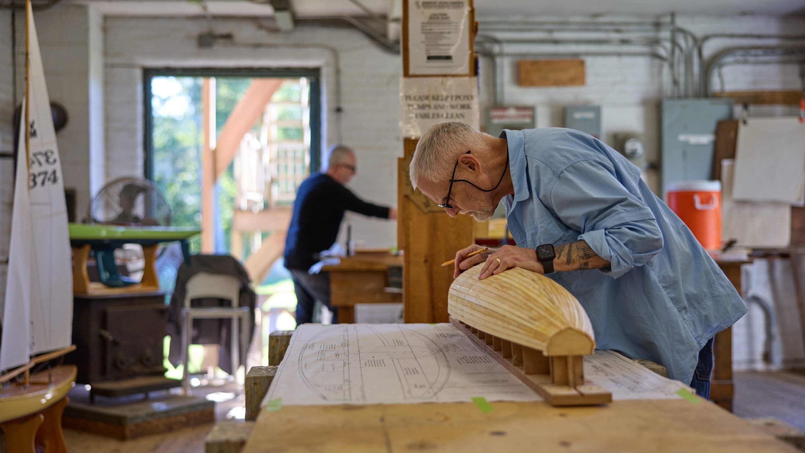
While growing up in western Pennsylvania, Bruce Richter spent countless hours in his dad’s workshop learning the ropes, building models, and making sawdust before getting sidetracked with garage bands, sports, and college. The urge to build returned around the time he and his wife Jan moved to New York City, although he quickly realized apartment living wasn’t exactly conducive to woodworking. The planets aligned when he discovered WoodenBoat School and Kerbs Boathouse in Central Park, home to over one hundred radio-control sailboats. Since then, Bruce took WoodenBoat School’s pond yacht construction course six times and served as former instructor Thom McLaughlin’s assistant before taking over as lead instructor a few years ago. Bruce has earned several national craftsmanship awards for the Vintage Marblehead RC sailboats he built at WBS. He is former Commodore of the 100-plus-year-old Central Park Model Yacht Club, has served as Class Coordinator of the US VMYG Vintage Marblehead fleet, is designer/art director of the vintage group’s publication The Model Yacht, and occasionally builds guitars. Following a career as a writer/creative director in major New York City advertising agencies and as president/executive creative director of his own marketing services firm, Bruce and wife Jan are beginning their next chapter in life as Blue Hill, Maine transplants.
This course is appropriate for students with some knowledge and experience. Basic knowledge and use of hand tools is required for most shop courses. Basic knowledge and ability to sail is required for most waterfront courses.
This course involves a low level of activity throughout the week including: occasional standing and working, seating is usually available, working on your own project at your own pace is common.
This is a six-day course ending Saturday
Other Sessions: September 1-7
Pond Yacht I: $385 (Includes CNC cut molds, strongback, keelson, planking, fin, and rudder.) Pond Yacht II: $169 (Includes materials to finish the boat other than sails, fittings and electronics.) Pond Yacht III: $35 (Shop supplies to help you continue your project.)
In this course each student will begin the construction of his/her own pond sailboat using the plank on frame process. This practice is similar to those used in building full-sized boats and allows for a flowing hull form that is beautiful on display and swift on the water. The course boat NORUMBEGA was designed by former instructor Thom McLaughlin. The class of this boat is known as Vintage Marblehead (VM) and is still actively sailed today under the guidance of the U.S. Vintage Model Yacht Group. The Marblehead class of small boat originated in 1932 using minimal design requirements of 50″ LOA and 800 square inches of sail. When fully rigged the boat is over 7′ tall, which makes it quite impressive from shore. The boat can be easily dismantled for transport. Construction of this pond yacht will pleasantly challenge and inform the builder. While group and one-on-one instruction will take place daily, students will also make decisions based on blueprints and developing an eye for form. During this week, the boat will be planked, faired, and the fin and rudder will be fabricated. Bruce will also discuss the steps that follow to complete the boat—decking, rigging, electronic installation, and painting.
Students who have started construction of their VM model in previous years at WoodenBoat School are also welcome to participate in this course to finish their boat. This week will be an excellent opportunity for further guidance. It will also provide inspiration to those individuals just beginning their boat and to view firsthand the final steps in construction.
This course is appropriate for students with some knowledge and experience. Basic knowledge and use of hand tools is required for most shop courses.
“Bruce Richter was an excellent instructor. He taught the pond yacht course in a knowledgeable, caring, and professional manner.”
T.S., Wilbraham, Massachusetts
“Bruce Richter taught a great course. I liked that he checked our work each evening and made note of our mistakes to correct the next day. He pulled together regular meetings to discuss theory. I especially enjoyed the pond yacht history lesson! Great teaching skills. Great personality and a sense of humor.”
J.J., Phoenix, Maryland

Register For This Course
Courses fill quickly, so don't delay if this is a course you want to take.
Related Courses
Woodcarving, carving name boards, introduction to woodworking.

- AMERICA'S CUP
- CLASSIFIEDS
- NEWSLETTERS
- SUBMIT NEWS

Straight Talking - Mast and Standing Rigging Terminology

Related Articles
Upcoming Events

- Search forums
Follow along with the video below to see how to install our site as a web app on your home screen.
Note: This feature may not be available in some browsers.
- Modelshipyard: Building Your Model
- Rigging: Covers all Standing and Running
rigging of the bowsprit on the schooner
- Thread starter Thread starter Alexander74
- Start date Start date Jul 5, 2021
- Watchers Watchers 2

Alexander74

- Jul 5, 2021

Explore Rhode Island's Blueways and Greenways

- Interactive Water Mapper
- Water Trail Maps
- Put-in/Boat Ramp List
- Books and Maps
- Paddle Safely
- Interactive Trail Mapper
- Trail List/Trail Maps
- Trail Safety
- Outfitters & Gear

Stay safe: please read our page about how to walk outdoors safely during COVID-19 .
Locustville pond.
41° 30.939' N 71° 43.032' W See this location in: Google Maps Map Server Acme Maps
This is a site for launching boats from trailers. Boat ramps can normally be used to launch canoes and kayaks but please do your best to keep the boat ramp clear for boat trailers.
Description & Overview:

Locustville Pond is a long, narrow, 82-acre pond. The gravel shoreline at the launch site is suitable for use as a boat ramp. No motors over 10 HP may be launched or hauled at this ramp. Much of the shoreline of the pond is lined with houses.
This site provides access to the following water bodies in the Pawcatuck River watershed: Locustville Pond.
Town: Hopkinton
Nearest Town Center: Wyoming, RI
Driving Landmarks: From I-95 north or south take Exit 3B for Route 138 West towards Hope Valley. This will put you on Route 138 west. Go 1/3 mile and bear left onto Route 3. Go 1.1 miles south on Route 3 and take a sharp right onto Bank Street. This turn is actually a "double turn" that takes you around a brick building that houses "The Remnant Shop," after which you are headed back northeast almost parallel to Route 3. Once on Bank Street, go 100 feet and turn left onto Fairview Avenue. Go 0.3 miles and look for a small road (Sunset Road) on the left. Turn left here and then go right at the fork just ahead of you. Go another 1/10 mile and look for the boat ramp on your left, where Sunset Road bends to the right.
Access & Waters:
Water 'Features' At Site: lake/reservior
Note: Because one boat launch can access, say, both a lake and a river or both the upstream and downstream portions of a river, not all paddling trips at a given site will necessarily encounter all of the features listed.
Type of Access: Boat ramp
ADA Accessible Boat Launch? no
Shoreline: Gravel shoreline suitable for use as a boat ramp
Float/Dock: no
Hours of Operation: Closed from 1/2 hr. after sunset to 5 am, except for fishing and boating
Parking: yes: 2 spaces, no overnight parking
ADA Accessible Parking Spaces? no
Nearby Amenities:
Outfitter: URE Outfitters on Route 3 in Hope Valley sells camping gear. Hope Valley Bait on Route 138 in Hope Valley rents canoes.
Do you have comments, corrections or additions to the information about this site?
Private feedback goes to the Blueways Alliance/RI Land Trust Council. We'll use your information to make this website better or pass it along to the people who can deal with physical issues at this site. Public comments are posted here (once they've been reviewed and approved) for all to see.
The data on this website come from many sources, including volunteers and organizations across the state of Rhode Island and nearby parts of Massachusetts. We have done our best to make sure the data are accurate and up to date, but any information critical to the success of your trip should be confirmed before you start. The maps and information on this website should not be substituted for nautical charts, topographic maps, or other more detailed maps and guides. We welcome corrections and additions. To send a correction or provide other feedback, please use our feedback form (see link above).
This site report was last updated on March 10, 2015
- Masting, rigging and sails

- Remember me Not recommended on shared computers
Forgot your password?
Help with understanding the rigging diagram
By Linda DOBLE February 9 in Masting, rigging and sails
- Reply to this topic
- Start new topic
Recommended Posts
Linda doble.

Link to comment
Share on other sites.
.thumb.jpeg.ffac2f8a24d212961a83eab4efb06a6c.jpeg "pond yacht rigging diagram")
These look like Occre rigging plans. What ship are you building? Do the yards have a hole near the end that the line passes through? On the HMS Beagle that line, I believe it is called the sheet, is attached to the lower corner of the sail and passes through a hole near the end of the yard then the line is run through the block as you indicate with your highlighter.
if you can let me know what ship you are building I will look at the rest of the plans from Occre ( assuming it is an Occre model) and confirm that is how Occre intends the rigging to be installed.
- mtaylor , allanyed and Gregory
Completed Build: HMS Beagle - Occre
Current Build: Frigate Diana - Occre https://modelshipworld.com/topic/33530-frigate-diana-by-rossr-occre-185/
On the Shelf: Santisima Trinidad Cross Section - Occre, NRG Half Hull, the US Brig Syren - Model Shipways and USF Essex - Model Shipways.
There is not a simple answer to your question, and that is a very simplified rigging diagram.
It is difficult for me to tell which line/s are represented by your green highlights.
They might be the sheet lines that would be attached to the lower corner of the sail ( not the middle of the yard ) and go through a series of blocks to be tied off/belayed on the deck or higher up in the rigging.
There are lines to control the yards and lines to control the sails. Some do a little of each.
The best starting advise you could get would come from a book such as Historic Ship Models by by Wolfram zu Mondfeld .
It has some very good rigging details, such as:

There will be help from many here, but the best help you will get is pointing you to the resources where this information can be found.
Another good rigging resource for beginners is Rigging Period Ship Models by Lennarth Petersson.
It provides a point to point guide for every line on the ship..

Petersson diagrams every line on the model like this.
Hope this helps.
- mtaylor and druxey
“Indecision may or may not be my problem.” ― Jimmy Buffett
Current builds: Rattlesnake (Scratch From MS Plans
On Hold: HMS Resolution ( AKA Ferrett )
In the Gallery: Yacht Mar y, Gretel , French Cannon
Roger Pellett
Linda, the line in question that you have marked in green is the sheet for the Royal Sail. It’s job is to pull the clew (corner) of the Royal Sail down against the TopGallant Yard, the yard immediately below. The line passes through a sheave in the outboard end of the TopGallant Yard. It then runs inboard along the yard where it is turned again by a block close to the yard’s centerline. From here it passes down to a belaying pin on the deck.
If you are modeling with set sails, it is attached to the clue of the Royal Sail as shown in the picture. If the Royal Sail is furled it will lead up to furled the Royal Sail, still attached to its clew. If you are modeling the vessel without sails, this line can be omitted.
- Gregory , Mark P , Keith Black and 2 others

Linda, if you're serious about learning about the rigging of 'period' ships, you might perhaps start with a copy of "The young Sea officers Sheet Anchor' by Darcy Lever. This book was first published in the first half of the 19th century by a professional seaman and has copious illustrations with good descriptions. You should be able to pick up a good second hand copy of one of the many reprints for $30 or less (for a first edition you'll need to take out a second mortgage).
- allanyed and mtaylor
I did a little research on the Occre web site and it looks like you are building their Amerigo Vespucci. I think this is probably Occre's most impressive model ship. I looked at the plans for the yards, and I believe there should be a small 1 mm hole near the end of the yard that the line passed through. This would represent the sheave that Roger mentioned and would be instead of the block shown on the diagram that Gregory provided. Both are correct, but I suspect the sheave in the yard became more common than the block on later ships.
There is a great build log of this ship on this form by a user named Daniel that you may want to look at if you haven't already. You may be a little further along than him, but he may have some thoughts on the rigging for this ship.
Good luck with your build.
- mtaylor and DanielD
The books mentioned in some the previous posts can be great resources, but may not be applicable to your ship if I am correct and it is the Amerigo Vespucci, as it was built much later in the 1930s.

Good Morning Linda;
To help you understand what is happening in the rigging diagrams you show, a simple rule can be applied:
The mast and sails on the left show the 'sheets'. All sails shown on the mast need a rope to keep their lower corners from flying up in the air, in which event the sail would hold no wind, and the ship would not move. The sheet performs this function, and is essentially the same on all the sails shown.
The right hand mast and sails show the ropes which are designed to do the exact opposite to the sheet, and to raise the lower corner of the sails to the yard when it is time to furl the sail. These are known as 'clew-lines'. To haul on the sheet opens the sail; to haul on the clew-line furls the sail. When the sheet is hauled, the clew-line must be 'paid-out', or slackened so that it runs free.
By far the best reference book I know of for ships of this era, which covers the rigging of such ships in great detail, is the 'Masting and Rigging of Clipper Ships and Ocean Carriers', by Harold A Underhill; first published in 1946. He was a very skilled modeller and draughtsman, and knew many of these ships personally. He also wrote several other books dealing with simiilar vessels, and produced a wide range of plans for such ships, which have very good masting and rigging details on them.
If you are building your model without sails, then the ends of the clew-line and the sheet would be shackled or tied together, so as to be ready in position when time came to fit the sail back to the yard.
(edit) I have just checked and the book is available online from £16, with many copies listed by different sellers, with different qualities and prices.
Wishing you all success with your modellling!
Previously built models (long ago, aged 18-25ish) POB construction. 32 gun frigate, scratch-built sailing model, Underhill plans.
2 masted topsail schooner, Underhill plans.
Started at around that time, but unfinished: 74 gun ship 'Bellona' NMM plans. POB
On the drawing board: POF model of Royal Caroline 1749, part-planked with interior details. My own plans, based on Admiralty draughts and archival research.
Always on the go: Research into Royal Navy sailing warship design, construction and use, from Tudor times to 1790.
Member of NRG, SNR, NRS, SMS
thank you Ross - Yes I am attempting the Amerigo Vespucci by Occre. (Great detective work) - I know it is above my skill level but when I saw this ship in the water (on YouTube) it gave me chills so I wanted it in my living room. yes I do indeed have 1mm holes at the end of the yards. I will have to study more about these sheet lines you all speak of. Roger I think you hit the nail on the head with your explanation. I wish they would at least show this line clearer in the photos. Some of the sails are set, while others not and they don’t really have a good photo showing this particular line on the furled (or half furled) sails.
Mark P - thank you as well, it’s so complicated, the rigging, and I am going to get this book as well… ‘I do have some of these books mentioned, but I have a problem with transferring the info into the current builds - sometimes I don’t even know what I’m looking for. Thanks for the help guys, much appreciated - cheers
- mtaylor and Mark P

8 hours ago, RossR said: I believe there should be a small 1 mm hole
As you already have the holes drilled, maybe something to consider for the future...... Using James Lees proportions in his The Masting and Rigging book (which may not apply on a modern training ship like the AV) and guessing the lower mast is about 8mm, the royal stay would be about 1/4 mm at 1:100 scale so the slot for the sheave (or hole itself for the line, if foregoing the sheave) would be less than 1/2mm. Regardless, a safe proportion would be to have a hole that is no more than about 0.0625 times the diameter of the lower mast where it pierces the deck.
PLEASE take 30 SECONDS and sign up for the epic Nelson/Trafalgar project if you would like to see it made into a TV series. Click on http://trafalgar.tv There is no cost other than the 30 seconds of your time. THANK YOU

One problem we have today is that with the demise of sailing ship as commercial carrier around WW1 also treatise on masting and rigging stopped to be written. So there is not much literature on full-scale practice post 1900.
Probably the reference book most applicable to AMERIGO VESPUCCI would be:
M IDDENDORF , F.L. (1903): Bemastung und Takelung der Schiffe.- 401 p., Kassel (reprint 1977 by Horst Hamecher).
but it is in German and no digital copies are available (to my knowledge), as there seems to be still some copyright on it.
The next best source then and one addressing the needs of the shipmodeller would be:
U NDERHILL , H.A. (1946): Masting & Rigging the Clipper Ship & Ocean Carrier.- 304 p., Glasgow (Brown, Son & Ferguson).
He focussed on late(r) 19th century commercial ships, not naval practice. Again no digital copy due to being still copyrighted.
There are many textbooks on rigging from the second half of the 19th century, including for naval practice, but since then things have evolved a lot (more wire rope in particular, not only for the standing rigging).
I must admit, I have never looked for Italian text books on rigging (though I do speak Italian). The closest would be Orazio Curti's book on shipmodelling, but he mainly uses mid- to late 19th century illustrations. Curti actually re-rigged the training schooner EBE from the 1920s that has been put up in the Museo della Scienza e Technologia in Milan. But she is a much smaller ship than the AMERIGO VESPUCCI ... I have to get around to put the detailed pictures I took of her last year onto my Web-site.
panta rhei - Everything is in flux

Ah, well, if it's the Amerigo Vespucci, Underhill would be a much better option, and you can still pick up a fairly cheap second hand copy!
There is also book on seamanship for the USCG Barque Eagle. It is published by the US Naval Institute Press. I believe that Eagle was built in Germany in the 193O’s. There is also Allan Villers’ The Way of a Ship. This is devoted to the steel hulled vessels still sailing in the 1930’s. The book includes several excellent illustrations of rigging drawn by Harold Underhill.
Join the conversation
You can post now and register later. If you have an account, sign in now to post with your account.

× Pasted as rich text. Paste as plain text instead
Only 75 emoji are allowed.
× Your link has been automatically embedded. Display as a link instead
× Your previous content has been restored. Clear editor
× You cannot paste images directly. Upload or insert images from URL.
- Insert image from URL
- Submit Reply
Recently Browsing 0 members
- No registered users viewing this page.
Modelshipworld - Advancing Ship Modeling through Research
SSL Secured
Your security is important for us so this Website is SSL-Secured
NRG Mailing Address
Nautical Research Guild 237 South Lincoln Street Westmont IL, 60559-1917
Model Ship World ® and the MSW logo are Registered Trademarks, and belong to the Nautical Research Guild (United States Patent and Trademark Office: No. 6,929,264 & No. 6,929,274, registered Dec. 20, 2022)
Helpful links.
- Articles Database
- NRG Home Page
- NRG Online Store
- Important: Our Guidelines
- Terms of Use
- Buildlog Index
About the NRG
If you enjoy building ship models that are historically accurate as well as beautiful, then The Nautical Research Guild (NRG) is just right for you.
The Guild is a non-profit educational organization whose mission is to “Advance Ship Modeling Through Research”. We provide support to our members in their efforts to raise the quality of their model ships.
The Nautical Research Guild has published our world-renowned quarterly magazine, The Nautical Research Journal, since 1955. The pages of the Journal are full of articles by accomplished ship modelers who show you how they create those exquisite details on their models, and by maritime historians who show you the correct details to build. The Journal is available in both print and digital editions. Go to the NRG web site (www.thenrg.org) to download a complimentary digital copy of the Journal. The NRG also publishes plan sets, books and compilations of back issues of the Journal and the former Ships in Scale and Model Ship Builder magazines.
Our Emblem ®
Nautical Research Guild ® and the NRG logo are Registered Trademarks, and belong to the Nautical Research Guild (United States Patent and Trademark Office: No. 6,999,236 & No. 6,999,237, registered March 14, 2023)
- Existing user? Sign In
- Latest Posts
- All unread content since my last vist
- Unread topics I have posted in
- Create New...
The Musings of a Hopeless Wanderer
Engaging in the eternal search for the meaning of life...or a good time.
- Netherlands
Monday, September 3, 2018
Tackling moscow by train and boat.
Our first full day in Moscow started fairly late since we were still catching up on sleep. Around 1, we finally were able to get our act together and get out the door.
We stopped by a cafe to get some breakfast and headed over to the Red Square. Since the festival is going on, we had to go through metal detectors. Once we cleared security, we reached the State Historical Museum which provided an entrance to the Red Square.

We walked the length of the Red Square, passing by the Kazan cathedral.

Under normal conditions, the Red Square is a large walking area with the State Historical Museum on one end and St. Basil's on the other end. On the sides is the Kremlin wall on one side and then the GUM shopping mall and the Kazan cathedral on the other side. Presently, the walking area has been considerably narrowed and the fesitval grounds occupying a large space between the Kremlin and the mall.
We even asked a stranger to take our picture!

After walking around the Red Square, we had to leave to meet up with our Metro Tour.
Moscow has famously pretty metro stations so metro tours are quite popular. We booked a relatively inexpensive tour through a tour group which met outside of the Red Square.
On our way, we passed by the Kremlin gardens and the tomb to the unknown soldier and the eternal flame.

We soon met up with our group which, fortunately, was only 5 people. Our guide told us that we were going to visit 8 stations during the 1.5 hour tour.
Honestly, a lot of the stations blended in to me so I won't be able to give you a detailed description of all of them. However, I did learn that there are 222 metro stations and the trains come every 2-3 minutes reliably. For that reason, Moscow > DC.
One of the first metro stations we visited had bronze statues all over of various depictions. Many of the statues had superstitions tied to them. For example, for a statue of the dog, it's held that if you rub the nose of the dog, you'll have good luck. Consequently, most of the statue is tarnished - except for the nose. I joked to Tomas that they probably rotate the "good luck" portion of the statue to ensure the entire statue gets polished.
However, I do remember some of the stations.
Novoslobodskaya is a station adorned with stained glass on the walls.

There was also Belarusskaya, which paid tribute to Belarus.

Another station which name I cannot remember but had pretty mosaics in the ceilings.

My favorite station was Komsomolskaya. It's the busiest station and a hub for other connecting trains. It was built during Statlin times and he wanted the station to embody beauty to set a good first impression to Russia.
I'd seen pictures of it beforehand since it's the most famous but it's so much more impressive in person.
Look at these ceilings!

Overall it was a very interesting tour. Not sure of any other city which could offer a metro tour. DC certainly can't...
After the tour, we headed back of the hotel to rest for a bit. We had purchased tickets to a tour hour boat down the Moscow river. The tickets were good for any time on any day and the boats left every 20min. We decided to knock the tour out that day and headed over to the pier.
We arrived at the pier and saw a boat by the company we had purchased from boarding. We approached and they shook their head and said it wasn't the right boat.
So we waited for another boat.
Another boat came along by the same company we had purchased from so weapproached them. Again - we were told it wasn't the right boat and the boat we were looking for was coming.
A third boat came along which was NOT by the company we had purchased from. By this point, it had been longer than 20min waiting and I was starting to suspect that the correct boat was actually one of the ones which turned us away. We approached the 3rd boat to ask if they knew which boat we should be on. However, when we approached, they waved us aboard without scanning our tickets.
So, we boarded the 3rd boat....which was definitely not ours.
We settled into an upper deck, open air table to take in the views.
We passed by pretty buildings.

The somewhat impressive cathedral of Christ the Savior.

This random statue.

After about hour on the cruise, Tomas remarked that it had been about an hour so we should be turning around soon. I reminded him that we actually had no idea how long this cruise was or where we would be dropped off. Since we were on the wrong boat.
Fortunately, it did turn around and took us back to the pier.
For dinner, we decided to go to this burger place, Black Star Burger, which our guide told us about. Tomas really liked his - I thought mine was OK. It was a decent size patty with a mountain of Cole slaw on top. We've realized that apparently Russians dislike getting their hands dirty while eating so some restaurants will give out gloves to use. This particular restaurant gave out black gloves.
Tomas modeling our dinner.

Since little mum has been asking about pictures which show my feet, I assume she wanted to see my new shoes. I recently bought Allbirds which are suppose to be super comfortable walking shoes which you wear without socks and can be washed. I didn't wear them too extensively beforehand, so that was probably my first error. I also didn't bring another pair of good walking shoes, which was likely my second error. The Allbirds were great the first two days without socks. Midway through the third day, my right foot was quite unhappy. Left foot was a trooper. So, now I have a bandaid on the heel of my right foot and wear socks.
No comments:
Post a comment.
IMAGES
COMMENTS
Im sifting the internet looking for information about pre-radio control Pond yacht rigging. Working rigging for sailing scale models. Before radio control, as I am sure all of you know, pond yachts reached a high degree of sophistication. Self tacking steering gear controlled by wind vanes, with ...
Work from the centre of the ship out and try to avoid locking yourself into difficult positions. A Rigging Tool presented in the Tools section of our Catalogue will be helpful when rigging. The various names for the Running Rigging are presented below. Fore brace. Fore lower topsail brace.
Rigging. After a short rummage about in an under the stairs cupboard I found the boom arm of the yacht rig.The boom is in good condition and fits to the mast base ( not sure how ). Boom arm. As far as I'm aware there is no jib parts, I do have the rudder and it looks OK. Don't know how efficient it will be though. Hopefully when the rigging ...
Posted May 22, 2022. Steering gear could have run the gamut from a toothed rack on the deck to allow the rudder to be set at various fixed settings, to lines rigged from the tiller to various sails, to wind vane or even clockwork steering mechanisms. All of these would work with a tiller, not a steering wheel.
This is the second in a series of videos with Tony Davis, the owner of Arey's Pond Boat Yard, explaining the proper way to rig a 14' catboat.Part 1 of the se...
Find rigging directions and diagrams for a 1 meter pond boat made in about 1945 from old books, magazines, or online sources. Learn how to sail and build pond yachts with this web page.
Two notes on the jumbo jib traveller block. First - the bottom must be shaped so it sits nicely on the bowsprit. Since the bowsprit is round, the bottom of the block needs to be curved to match it. Second - the block has a wire on top where the jumbo jib boom hooks on. This wire should not be glued in now.
A user asks for rigging details for a 1950's pond sailboat restoration project. Other users suggest some books and forums that may help, but no diagrams are available.
There are just too many variables. For example, a 1920's vintage boat could be either gaff rigged (square sails) or Marconi rigged (triangular sails). Each has different rigging. Pond yachts could be either free sailing or self steering. There are some web sites that deal specifically with pond yachts.
A short video of a recently built 24" vintage style gaff rigged Pond Yacht under sail. She is currently available for sale at http://www.haycroftpondyachts.c...
Rigging screws with the upper thread swaged onto the wire (stud rigging screws) are threaded for extension by twisting the body clockwise. Fit this type of rigging screws to the standing rigging. Fit all other rigging screws to the yacht's chain plates Stud rigging screws. with the left-hand thread downwards.
I was given an old pond yacht which I want to make into a display model. It is has a GRP hull, lead keel and ply deck with rudimentary wooden spars. It is 36" loa, 9" beam but too tall for the landing window at 62". It was made years ago by my brother who was a crafts teacher as a prototype for a class project with brazed brass deck fittings etc.
radiosailingshop : pond yachts & parts - sailsetc drawings rig kits & rig plans boom kits masts alum & carbon fibre boom sections vangs - goosenecks mast, boom & rigging parts hull & deck fittings rudders fins and bulbs sails & sailmaking winches & drums radios servos batteries etc accessories, covers & misc. fasteners screws, bolts, nuts spare parts print your own catalogue free boat ...
A sailboat's standing rigging is generally built from wire rope, rod, or occasionally a super-strong synthetic fibered rope such as Dyneema ®, carbon fiber, kevlar or PBO. 1×19 316 grade stainless steel Wire Rope (1 group of 19 wires, very stiff with low stretch) is standard on most sailboats. Wire rope is sized/priced by its diameter which ...
Credit: Bill Tripp Design. The Bermudan rig is the all-rounder, able to perform well at all angles of sail. It is efficient upwind, while downwind the sail area can be significantly boosted with a big gennaker or spinnaker. For good reasons, it is the first choice for nearly every modern sailing yacht up to around 60 to 65 metres for cruising ...
This is a six-day course ending Saturday. Other Sessions: September 1-7. Pond Yacht I: $385 (Includes CNC cut molds, strongback, keelson, planking, fin, and rudder.) Pond Yacht II: $169 (Includes materials to finish the boat other than sails, fittings and electronics.) Pond Yacht III: $35 (Shop supplies to help you continue your project.) In this course each student will begin the construction ...
Techniques and suppliers have obviously progressed or changed in last 100 years but some advice is as relevant today as then. From restoration manual p1 first line: "Some important Don'ts. Don't bring boats, tools, work in progress from workshop into kitchen without an express invitation.". Cheers.
Details of the rigging of the forearm braces. Beginning of the running rigging on the eye in the deck on each side of the mainmast.View attachment 246291 Further, through the two-pulley block on the mast, the ropes diverge and follow to the block on the forehand View attachment 246293 Pass through the block on the yard and return to the mainmast
The standing rigging is the fixed / structural stays which support the mast. These are often split into fore & aft (forestay and backstay) and then the lateral rigging (side shrouds). In wire rigging world, people often refer to the Cap shroud (running all the way from deck to masthead) and intermediate stays, however when we start talking rod ...
A short spar, normally kept stowed, which may be used to push the clew of a jib away from the boat when the boat is running downwind. (this definition for modern yacht) Bingo!!! I found one! The way your diagram showing is not commonly used. The more common use of spreaders by the way attaching ring bolts and tackle with blocks
Locustville Pond is a long, narrow, 82-acre pond. The gravel shoreline at the launch site is suitable for use as a boat ramp. No motors over 10 HP may be launched or hauled at this ramp. Much of the shoreline of the pond is lined with houses. This site provides access to the following water bodies in the Pawcatuck River watershed: Locustville Pond.
The right hand mast and sails show the ropes which are designed to do the exact opposite to the sheet, and to raise the lower corner of the sails to the yard when it is time to furl the sail. These are known as 'clew-lines'. To haul on the sheet opens the sail; to haul on the clew-line furls the sail.
Tackling Moscow by Train and Boat Our first full day in Moscow started fairly late since we were still catching up on sleep. Around 1, we finally were able to get our act together and get out the door. We stopped by a cafe to get some breakfast and headed over to the Red Square. Since the festival is going on, we had to go through metal detectors.